-
 Posted On Gaya Hidup
Mulai Hari dengan Segar Manfaat Lari Pagi Setiap Hari


Manfaat Lari Pagi Setiap Hari – Memulai hari dengan kegiatan fisik yang bermanfaat dapat memberikan dorongan positif bagi tubuh dan…
-
 Posted On Gaya Hidup
Menikmati Kesehatan Manfaat Minum Jus Buah untuk Hidup Sehat
Manfaat Minum Jus Buah untuk Hidup Sehat – Jus buah adalah minuman alami yang menyegarkan dan bermanfaat bagi kesehatan. Dalam…
-
 Posted On Gaya Hidup
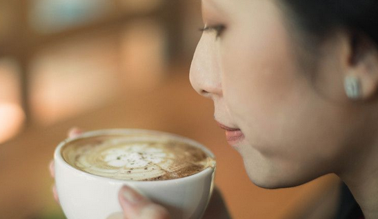
Mengenal Manfaat Minum Kopi untuk Kesehatan dan Kehidupan
Mengenal Manfaat Minum Kopi – Minum kopi telah menjadi bagian dari rutinitas sehari-hari bagi banyak orang di seluruh dunia. Selain…
-
 Posted On Gaya Hidup
Menjaga Kesehatan dan Kualitas Hidup Manfaat Pola Hidup Sehat
Manfaat Pola Hidup Sehat – Dalam era modern yang serba cepat ini, gaya hidup yang sehat seringkali menjadi prioritas rendah…
-
 Posted On Gaya Hidup
Menjaga Kesehatan Panduan Praktis untuk Menjalani Hidup Sehat
Dalam kehidupan yang serba cepat seperti saat ini, menjaga kesehatan sering kali menjadi hal yang diabaikan. Banyak orang terjebak dalam…